I received a drawing file and was asked to make some edits. What I found (or did not find) in this file prompted me to write this post.
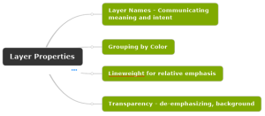
The primary purpose of layers in a CAD file is to set the visual qualities of drawing content. However, in this post I want to focus on how layers are used to convey meaning. That meaning starts with the layer property called Name. Other layer properties control the visual aspect such as color, lineweight, and linetype. You have to admit life would be pretty boring without these other properties.
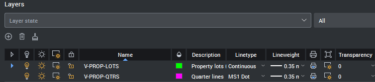
Layer Properties are displayed in a table. The header row shows the name of each property. This table is where you control the settings for each property in a convenient and intuitive user interface.
What meaning do you convey with each property setting? Let’s take a closer look at each one.
Name – The layer name performs multiple jobs. First, say what you mean. Second, format for convenience in sorting and grouping. Third, use reusable phrases for consistency. A National CAD Standard example is V-PROP-LOTS. V means the Surveying discipline. PROP means property as in land ownership lines. LOTS means a form of property indicating building lots in a subdivision.
Description – maybe your name is not enough to say what drawing objects are included and excluded, if that helps clarify your intent.
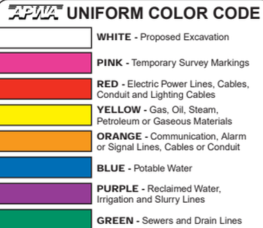
Color – a good way to visually group objects using color. Some examples, building footprint lines are blue, text is yellow, sanitary sewer lines are green. If your specialized discipline has a color code for similar purposes you can choose to be consistent with that standard by incorporating that into your layer standard.
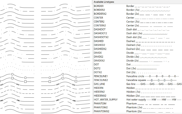
Linetype – A continuous linetype is a solid line. Other linetypes are commonly used to indicate a status. For example elevation contours in a site plan are commonly differentiated by existing (dashed), vs design (solid). Other linetypes can contain letters or symbols to indicate barbed wire (with an x) or a water line (with a W).
Lineweight – A thick line is used to call attention to more important objects like a building footprint. Thin lines are important to provide background context. There are varying thicknesses in between these two extremes that help you convey a meaning of relative size, importance, or both.
Transparency – commonly used for image underlays or external referenced objects. Transparency provides a way to de-emphasize drawing objects without eliminating them entirely from view. Images have their own property Fade used to specifically alter that object. Examples are the best way to explain the use of transparency property of a layer.
Layer Standards – A good practice for consistent use of layers is to develop and document an organized set of rules for each layer and its properties. Having those rules in writing will help you to communicate your intended use and meaning for each layer. All the people that could really use this information have left the room by now. If you know someone who consistently produces “Bad CAD” you have my sympathy.
Downstream users – The drawing file is a vehicle to display your deliverable work on sheets in a plan set. The visual output in a hardcopy print or pdf document may not reveal this level of detail organized by layers within the drawing file. You most likely have hundreds of layers in a complex drawing. Think of a drawing file as a database. A database cannot be a database without rules. When someone else receives a copy of your drawing they may use its content to add to a larger dataset, a GIS basemap for example. Other users may want to extract quantities from objects in your drawing file. Your reputation is on the line each time someone opens your drawing file.
User Interface Terminology.
BricsCAD has a Layers Panel to display layer properties. The command LAYERSPANELOPEN is one way to display this panel.
AutoCAD has a Palette called the Layer Properties Manager. The LAYER command is one way to open the Layer Properties Manager.

Recent Comments